Wednesday, October 12, 2011

NOVEL "SUATU KETIKA" KARYA PUJANGGA PIPING


Novel ini berisi beberapa cerita pendek yang dibuat oleh pujangga piping semasa bekerja di PFCE dan berkantor di Gedung Maju Junction di sekitaran Sultan Ismail Kuala Lumpur.

Cerita-cerita pendek itu merupakan kumpulan cerita-cerita pendek yang pernah di buat di dalam blog ini dan diedit kembali menjadi suatu bacaan yang mungkin sedikit lebih baik dari yang dilihat atau dibaca dalam blog ini.

Inti cerita adalah cerita-cerita ini adalah cerita khayalan saja atau cerita fiksi saja dimana diceritakan  Ucup yang nama aslinya Rod Steward punya impian mendapatkan seorang Gadis Malaysia saat dia bekerja di Malaysia namun si Ucup ini telah mempunyai kekasih di Indonesia yang bernama Aminah.

Tapi intinya Cinta tak boleh terbagi dan bila ingin berbagi orang yang kita kasihi lebih awal akan merasakan perbedaan itu.


Akhir cerita Ucup Alias Rod Steward alias Sammy memutuskan untuk tidak kembali ke Malaysia dan mencari kerja di Indonesia saja bukan karena cintanya sama Aminah tapi ingin melupakan cintanya terhadap gadis Malaysia tersebut.


Kalau penasaran baca aja cerita demi cerita di blog ini atau bisa download di ziddu untuk rangkuman cerita cerita pendek tersebut.


Adapun judul-judul cerita pendek yang terdapat di dalam novel ini adalah :


1.Demi Cinta  ……………………………………………………….            
2.Demi Cinta Dua  ………………………………………………….           
3.Secawan Cinta Kokoh  ………………………………………..           
4.Cinta Yang Bermimpi  ………………………………………….
5.Cinta Kereta Api  ………………………………………………….
6.Pupus Bukan Superman  ……………………………………..
7.How Do I Live Without You  ………………………………..
8.Ketika Aku Cape Memikirkan Kamu – When I was
   Tired to Think of Yo  ……………………………………………
9.Ketika Aku Melihat Cahaya Cinta Di Matamu  …….
10.Ketika Cinta Ingin Memiliki Yang Lain Lagi  ………
11.Kelakuan Cinta Part (The Story of Madu Tiga)  …
12.Bila Cinta Tak Mengerti Aku 


Salam Kuala Lumpur, 12 October 2011

Thursday, October 6, 2011

SELAMAT ATAS TERSELENGGARANYA SEMINAR & GALA DINNER ULTAH MMI & KMI 6 OCTOBER 2011 - MAAF SAYA NGGAK BISA HADIR

PRESS RELEASE

ULTAH MILIS MIGAS INDONESIA (MMI) KE – 10 DAN KMI AWARD 2011
BALLROOM XXI DJAKARTA THEATRE, 06 OKTOBER 2011

KMI akan Gelar  10 Tahun  Millis Migas 8 Tahun Komunitas Migas dan  KMI Award 2011 dengan mengadakan “Seminar dan Apresiasi Pemberian Penghargaan”

Tidak disangsikan keberadaan industri minyak dan gas bumi (Migas) di Indonesia tidak kurang dari 40 tahun telah menjadi lokomotif pergerakan ekonomi bangsa. Saat ini-pun kontribusinya cukup signifikan yakni sekitar 30 % terhadap penerimaan negara. Belum lagi perannya bagi terwujudnya ketahanan energi nasional .

Namun dalam perjalanannya, terdapat pasang surut pengelolaan Migas di tanah air. Akibatnya produksi migas pada beberapa tahun terakhir ini cenderung menurun.  Banyak faktor  yang menyebabkan penurunan produksi ini diantaranya adanya laju  penurunan alamiah produksi (decline rate) yang terkategori tinggi yakni 12% karena kondisi lapangan yang tua, minimnya investasi eksplorasi untuk menemukan cadangan baru, masalah perijinan lahan, permasalahan dalam manajemen proyek, unplanned shutdown, dan lain sebagainya.

Kecenderungan turunnya produksi Migas tentunya akan berpengaruh terhadap penerimaan negara dan struktur APBN  (Anggaran Penerimaan dan Belanja Negara) serta keamanan pasokan Energi (Migas) domestik. Untuk itulah, masalah produksi Migas ini sebagai salah satu masalah krusial pengelolaan Migas di tanah air penting untuk terus didiskusikan dengan berbagai pihak dan berbagai disiplin ilmu, sehingga bisa mendapatkan strategi dan solusinya secara lebih komphrehensif.

Menyadari hal tersebut, Komunitas Migas Indonesia (KMI) sebagai organisasi profesi multi disiplin ilmu bekerjasama dengan MMI (Millist Migas Indonesia) dan didukung BPMIGAS (Badan Pelaksana  Kegiatan Usaha Hulu Migas) , akan menyelenggarakan seminar dengan tema “ Menatap Masa Depan Produksi Migas Indonesia” dan pemberian apresiasi penghargaan bagi para insan Migas di Indonesia terutama 10 tahun terakhir melalui “KMI Award”.  Acara tersebut juga sekaligus merayakan 10 tahun mailing list Migas yang selama ini telah berperan sebagai media pertukaran informasi insan migas.

Seminar dan Award yang juga di dukung penuh oleh BPMIGAS  ini, mengangkat tema “Menatap Masa Depan produksi Migas Indonesia” dan Pemberian Apresiasi Penghargaan bagi para Insan Migas di Indonesia melalui KMI Award. Acara ini sekaligus merayakan 10 tahun Milis Migas yang selama ini telah berperan sebagai media pertukaran informasi para insan migas.

“Ini bentuk kontribusi KMI untuk membangun Indonesia lebih baik, khususnya Industri Migas”, demikian tutur Ketua Harian KMI, S. Herry Putranto.

Acara Seminar dan Award ini akan berlangsung pada 6 Oktober 2011, bertempat di Ballroom XXI Djakarta Theatre - Jakarta. Di samping membahas masalah Produksi Migas Indonesia, dalam seminar ini juga mengangkat sub topik mengenai Tender Migas, yang tentunya dengan menghadirkan beberapa nara sumber yang kompeten baik dari kementrian Keuangan, Kontraktor Migas, DPR RI, dan Tim Peningkatan dan Percepatan Produksi Migas (TP3M) Kementrian ESDM.

Untuk Apresiasi Pemberian Penghargaan atau KMI Award 2011, akan di berikan pada tokoh yang berperan penting dalam kemajuan industri migas, dengan mengambil beberapa unsur baik dari pemerintah, perusahaan Migas maupun masyarakat.  Pemilihan atau voting di lakukan dengan melibatkan sekitar 15000 anggota milis (online) Profesional Migas Indonesia melalui link www.migas-indonesia.org

Sejarah Milis Migas Indonesia (MMI)

Milis Migas Indonesia (http://groups.yahoo.com/group/Migas_Indonesia) yang di dirikan pada tanggal 25 Agustus 2001 dan kini sudah beranggotakan kurang lebih 15000 orang dari berbagai perusahaan/institusi di dalam maupun di luar negeri, adalah spirit yang menjiwai  pembentukan Keluarga Besar Migas Indonesia.

Pada tanggal 16 Februari 2008, Aksi Sosial Peduli Sesama memulai kegiatan pertamanya untuk membantu korban banjir besar di Jakarta, selanjutnya tanggal 25 Agustus 2002 mulai di luncurkan secara resmi  Portal Internet Migas Online (http://www.migas-indonesia.com/), kemudian berikutnya adalah pendirian Organisasi Profesi Komunitas Migas Indonesia (KMI) pada tanggal 17 November 2003, Koperasi Mitra KMI pada September 2004, Jurnal KMI pada 17 November 2004 dan Migas Indonesia Network (www.migas-indonesia.net) pada 17 November 2006.

Pendiri Milis Migas Indonesia ini adalah Alm. Swastioko Budhi Suryanto, selain menjadi salah satu Administrator Milis, beliau juga di daulat oleh anggota untuk menjabat sebagai Ketua Umum Komunitas Migas Indonesia (KMI) sejak di dirikan pada tanggal 17 November 2003


Sumber : Millis Migas Indonesia

Wednesday, October 5, 2011

AN INTRODUCTION TO VALVES - ONLY THE BASIC - BELLOW SEALED VALVES

BELLOW(S) SEAL(ED) VALVES

In this article, the author Mr. Satish Chidrawar (at the bottom of this page you will find more about the author) first reviews the construction, design and operation of the bellow seal. He then provides various examples of where bellow seal valves are use.

Leakage at various points in pipelines found in chemical plants creates emissions. All such leakage points can be detected using various methods and instruments and should be noted by the plant engineer. Critical leakage points include flanged gasket joints and the valve / pump gland packing, etc. Today the chemical process industry is gearing itself towards safer technology for better environmental protection and it has become every process engineer's responsibility to design plants that limit damage to the environment through the prevention of leakage of any toxic chemicals.
Leakage from the valve gland or stuffing box is normally a concern for the maintenance or plant engineer. This leakage means:
 a) Loss of material   b) Pollution to the atmosphere   c) Dangerous for plant employees.


VALVOLA
is well qualified to provide technological assistance and high tech Bellow Sealed Valves for applications involving hazardous and difficult-to-handle fluids and gases.


Bellow Sealed Gate Valve

For example, take the case of a steam leakage through the valve gland. At 150 PSI, a clearance of just 0.001" through the gland will mean a leak at the rate of 25 lb/hour. This equates to a loss of USD 1.2 per eight hour shift, or USD 1,100 per year. Similarly, a tiny drop of 0.4 mm diameter per second results in a waste of about 200 litres per year of costly oil or solvent. This leakage can be reduced considerably by using the bellow seal valve. This article will now consider the construction and operation of the bellow seal.

Bellow construction
 The bellow cartridge is welded to both the valve bonnet and the valve stem. The bellow cartridge has a number of convolutions and these convolutions become compressed or expanded depending upon the movement of valve stem. (Scientifically speaking the bellow gets compressed when the valve is in the open position and expanded when the valve is in the closed condition). It is important to properly install the valve bodies. The bellow can be sealed to the valves in two different ways. Firstly, the bellow can be welded to the valve stem at the top and the valve body on the bottom. In this case the process fluid is contained inside the bellow or in second method the bellow is welded to the valve stem at the bottom and the body on the top. In this case the process fluid is contained in the annular region between the valve bonnet and bellow (from the outside).

The bellow is a critical component and forms the heart of the bellow seal valves. To avoid any twisting of the bellow the valve must have a stem with linear movement only. This can be achieved using a so-called sleeve-nut at the yoke portion of the valve bonnet. A handwheel is fitted onto the sleeve-nut which effectively transfers a rotary motion of the handwheel into a linear motion in the valve stem.


Bellow Sealed Gate Valve

Bellow types
 There are two main types of bellow: the Forged Bellow and the Welded Bellow. Formed-type bellows are made from rolling a flat sheet (thin wall foil) into a tube which is then longitudinally fusion welded. This tube is subsequently mechanically or hydrostatically formed into a bellow with rounded and widely spaced folds. The welded leaf type bellow is made by welding washer-like plates of thin metal together at both the inner and outer circumference of the washers - like plates. A welded leaf bellow has more folds per unit length as compared to forged bellows. Thus, for the same stroke length, forged bellows are two to three times longer than their welded leaf counterparts.

Reportedly, mechanically forged bellows fail at random spots, while the welded leaf usually fails at or near a weld. To ensure full penetration of bellow ends and end coller welding it is advisable to fabricate using micro plasma welding.

Bellow design
 The multi-ply bellow design is preferred for handling higher pressure fluids (generally two or three plies of the metal wall). A two ply bellow can increase its pressure rating by 80% to 100% as compared to a single ply bellow of the same thickness. Alternatively, if a single ply bellow of a thickness equivalent to a pressure rating of a two ply bellow is used, the stroke length is reduced. Thus, a multi-ply bellow design offers a distinct advantage over a single ply bellow. It is clear that the bellow is subject to metal fatigue and this fatigue can induce weld failure. The bellow fatigue life is affected by the material of construction, fabrication technique, stroke length and stroke frequency, in addition to the usual parameters such as fluid temperature and pressure.

Bellow materials
 The most popular stainless steel bellow material is AISI 316Ti which contain Titanium to withstand high temperatures. Alternatively, Inconel 600 or Inconel 625 improve fatigue strength and corrosion resistance as compared with stainless steel bellows. Similarly, Hastalloy C-276 offers greater corrosion resistance and fatigue strength than Inconel 625. Fatigue resistance can be improved by using a multiply bellows system and reducing the stroke length; this can significantly increase the bellow service life.

Valve options
 The most common valve types to be fitted with bellow seals are the gate and globe designs (see Figure 1).These are very suited for use with bellows due to their internal construction and axial movement of the valve stem.
 Based on available information, it seems that current bellow seal valves range in size from 3 mm NB to 650 mm NB. Pressure ratings are available in from ANSI 150# to 2500#. Material options for the valves include carbon steel, stainless steel and exotic alloys.

Applications
 Heat transfer media: hot oil is commonly used in industries such as synthetic fibres / POY (Partially Oriented Yarn). However, there is always a risk of fire due to hot oil spillage on highly inflammable chemicals. Here, bellow seal valves can stop the leakage.

Vacuum / ultra high vacuum: some applications require a vacuum pump to continually extract air from a pipeline. Any conventional valves installed on the pipeline can allow external air to enter the pipeline thorough the valve stuffing box. Hence the bellow seal valve is the only solution to prevent air from passing through the stuffing box.
 Highly hazardous fluids: for media such as chlorine (see Figure 2), hydrogen, ammonia and phosgene, the bellow seal valve is an ideal design as leakage through the gland is totally eliminated.
 Nuclear plant, heavy water plant: in instances where radiation leakage is to be prevented at all times, the bellow seal valve is the ultimate choice.
 Costly fluids: in some applications leaks need to be avoided simply because of the high cost of the fluid. Here, an economic assessment often favours the use of bellow seal valves.
 Environmental standards: around the world, standards regarding emissions and the environment are getting more stringent day by day. It can therefore be difficult for companies to expand within existing premises. With the use of bellow seal valves, expansion without additional environmental
 damage is possible.

About the Author
 Mr. Satish Chidrawar is CEO of Valvola Corporation in Mumbai, India. He has more than 35 years of diversified Engineering experience, including more than 21 years in "Valve Engineering". Mr. Chidrawar is also responsible for developing & maintaining technical methods used in bellow sealed valves for various critical conditions. He holds a diploma in Mechanical Engineering from Board of Technical Education - Maharashtra, India and has authored various papers on bellow seal valves.

from www.wermag.org 

AN INTRODUCTION TO VALVES - CHECK VALVE

CHECK VALVE

Check valves are "automatic" valves that open with forward flow and close with reverse flow. The pressure of the fluid passing through a system opens the valve, while any reversal of flow will close the valve. Exact operation will vary depending on the type of check valve mechanism. Most common types of check valves are swing, lift (piston and ball), butterfly, stop and tilting-disk.
Image of a typical Check valve (swing type).

TYPES OF CHECK VALVES

Swing check valve
A basic swing check valve consists of a valve body, a bonnet, and a disk that is connected to a hinge. The disk swings away from the valve-seat to allow flow in the forward direction, and returns to valve-seat when upstream flow is stopped, to prevent backflow.
The disc in a swing type check valve is unguided as it fully opens or closes. There are many disk and seat designs available, in order to meet the requirements of different applications. The valve allows full, unobstructed flow and automatically closes as pressure decreases. These valves are fully closed when flow reaches zero, in order to prevent backflow. Turbulence and pressure drop in the valve are very low.

Lift check valve
The seat design of a lift-check valve is similar to a globe valve. The disc is usually in the form of a piston or a ball.
Lift check valves are particularly suitable for high-pressure service where velocity of flow is high. In lift check valves, the disc is precisely guided and fits perfectly into the dashpot. Lift check valves are suitable for installation in horizontal or vertical pipe-lines with upward flow.
Flow to lift check valves must always enter below the seat. As the flow enters, the piston or ball is raised within guides from the seat by the pressure of the upward flow. When the flow stops or reverses, the piston or ball is forced onto the seat of the valve by both the backflow and gravity

from www.wermag.org

Tuesday, October 4, 2011

AN INTRODUCTION TO VALVES - BUTTERFLY VALVE

BUTTERFLY VALVE

A butterfly valve is a quarter-turn rotational motion valve, that is used to stop, regulate, and start flow. Butterfly valves are easy and fast to open. A 90° rotation of the handle provides a complete closure or opening of the valve. Large Butterfly valves are usually equipped with a so-called gearbox, where the handwheel by gears is connected to the stem. This simplifies the operation of the valve, but at the expense of speed.

Advantages of butterfly valves
Compact design requires considerably less space, compared to other valves
Light in weight
Quick operation requires less time to open or close
Available in very large sizes
Low-pressure drop and high-pressure recovery

Disadvantages of butterfly valves
Throttling service is limited to low differential pressure
Cavitation and choked flow are two potential concerns
Disc movement is unguided and affected by flow turbulence

Image of a typical Butterfly valve, Lug Wafer type design.

TYPES OF BUTTERFLY VALVES

Butterfly valves has a short circular body, a round disc, metal-to-metal or soft seats, top and bottom shaft bearings, and a stuffing box.

The construction of a butterfly valve body varies. A commonly used design is the wafer type that fits between two flanges. Another type, the lug wafer design, is held in place between two flanges by bolts that join the two flanges and pass through holes in the valve's outer casing. Butterfly valves are even available with flanged, threaded and butt welding ends, but they are not often applied.

SEAT DISK AND STEM OF A BUTTERFLY VALVE

Stopping flow is achieved by the valve disk sealing against a seat that is on the inside diameter periphery of the valve body. Often an elastomeric seat material will be used. Disk and stem of a butterfly valve consists of two parts, and there a two methods to be fastened together.

In the first method, the disk is bored through and secured to the stem with bolts or pins. The second method involves boring the disk as before, then shaping the upper stem bore to fit a squared or hex-shaped stem. This method allows the disk to "float" and seek its center in the seat.

TYPICAL APPLICATIONS OF BUTTERFLY VALVES

A butterfly valve can be used in many different fluid services and they perform well in slurry applications. The following are some typical applications of butterfly valves:
Cooling water, air, gases, fire protection et cetera
Slurry and similar services
Vacuum service
High-pressure and high-temperature water and steam services

from www.wermag.org

AN INTRODUCTION TO VALVES - BALL VALVE

BALL VALVE

A ball valve is a quarter-turn rotational motion valve that uses a ball-shaped disk to stop or start flow. If the valve is opened, the ball rotates to a point where the hole through the ball is in line with the valve body inlet and outlet. If the valve is closed, the ball is rotated so that the hole is perpendicular to the flow openings of the valve body and the flow is stopped.

Advantages of using ball valves:
Quick quarter turn on-off operation
Tight sealing with low torque
Smaller in size than most other valves

Disadvantages of ball valves:
Conventional ball valves have poor throttling properties
In slurry or other applications, the suspended particles can settle and become trapped in body cavities causing wear, leakage, or valve failure.

TYPES OF BALL VALVES

Ball valves are basically available in three versions: full port, venturi port and reduced port.

The full-port valve has an internal diameter equal to the inner diameter of the pipe.
 Venturi and reduced-port versions generally are one pipe size smaller than the line size.

Ball valves are manufactured in different body configurations and the most common are:
Top entry ball valves allow access to valve internals for maintenance by removal of the valve bonnet-cover. It is not required to be removed valve from the pipe system.
Split body ball valves consists of a two parts, where one part is smaller as the other. The ball is inserted in the larger body part, and the smaller body part is assembled by a bolted connection.

The valve ends are available as butt welding, socket welding, flanged, threaded and others.

MATERIALS OF BALLS AND SEATS

Balls are usually made of several metallics, while the seats are from soft materials like Teflon, Neoprene, and combinations of these materials. The use of soft-seat materials imparts excellent sealing ability. The disadvantage of soft-seat materials (elastomeric materials) is, that they are not can be used in high temperatures processes.

For example, fluorinated polymer seats can be used for service temperatures from −200° (and larger) to 230°C and higher, while graphite seats may be used for temperatures from ?° to 500°C and higher.
BALL VALVE STEM DESIGN

The stem in a ball valve is not attached to the ball. Usually it has a rectangular portion at the ball, and that fits into a slot cut into the ball. The enlargement permits rotation of the ball as the valve is opened or closed.

BALL VALVE BONNET

The bonnet of a ball valve is fastens to the body, which holds the stem assembly and ball in place. Adjustment of the bonnet permits compression of the packing, which supplies the stem seal. Packing material for ball valve stems is usually Teflon or Teflon-filled or O-rings instead of packing.

BALL VALVES APPLICATIONS

The following are some typical applications of ball valves:
Air, gaseous, and liquid applications
Drains and vents in liquid, gaseous, and other fluid services
Steam service

from www.wermag.org

AN INTRODUCTION TO VALVES - PLUG VALVE

PLUG VALVE

A plug valve is a quarter-turn rotational motion valve that use a tapered or cylindrical plug to stop or start flow. In the open position, the plug-passage is in one line with the inlet and outlet ports of the valve body. If the plug 90° is rotated from the open position, the solid part of the plug blocks the port and stops flow. Plug valves are similar to ball valves in operation.

Advantages of using plug valves:
Quick quarter turn on-off operation
Minimal resistance to flow
Smaller in size than most other valves

Disadvantages of plug valves:
Requires a large force to actuate, due to high friction.
NPS 4 and larger valves requires the use of an actuator.
Reduced port, due to tapered plug.

TYPES OF PLUG VALVES AND SEALING

Plug valves are available in a nonlubricated or lubricated design and with several styles of port openings. The port in the tapered plug is generally rectangular, but they are also available with round ports and diamond ports.
Plug valves are also available with cylindrical plugs. The cylindrical plugs ensure greater port openings equal to or larger than the pipe flow area.
Lubricated plug valves are provided with a cavity in the middle along there axis. This cavity is closed at the bottom and fitted with a sealant-injection fitting at the top. The sealant is injected into the cavity, and a check valve below the injection fitting prevents the sealant from flowing in the reverse direction. The lubricant in effect becomes a structural part of the valve, as it provides aflexible and renewable seat.
Nonlubricated Plug Valves contain an elastomeric body liner or a sleeve, which is installed in the body cavity. The tapered and polished plug acts like a wedge and presses the sleeve against the body. Thus, the nonmetallic sleeve reduces the friction between the plug and the body.

PLUG VALVE DISK
Rectangular port plugs are the most common port shape. The rectangular port represents 70 to 100 percent of the internal pipe area.
Round port plugs have a round opening through the plug. If the port opening is the same size or larger than the inside diameter of the pipe, a full port is meant. If the opening is smaller than the inside diameter of the pipe, a standard round port is meant.
Diamond port plug has a diamond-shaped port through the plug and they are venturi restricted flow types. This design is suitable for throttling service.

TYPICAL APPLICATIONS OF PLUG VALVES

A plug valve can be used in many different fluid services and they perform well in slurry applications. The following are some typical applications of plug valves:
Air, gaseous, and vapor services
Natural gas piping systems
Oil piping systems
Vacuum to high-pressure applications

From www.wermag.org

AN INTRODUCTION TO VALVES - GLOBE VALVE

GLOBE VALVE

A globe valves is a linear motion valve and are primarily designed to stop, start and regulate flow. The disk of a globe valve can be totally removed from the flowpath or it can completely close the flowpath.
The fundamental principle of the globe valve operation is the perpendicular motion of the disk away from the seat. This ensures that the ring-shaped space between the disk and seat ring gradually close as the valve is closed. This property gives a globe valve reasonably good throttling capability. Therefore, the globe valve can be used for starting and stopping flow and to regulate flow.

Advantages of using globe valves:
Good shutoff capability
Reasonably good throttling capability

The major drawbacks to the use of a globe valve are:
Higher pressure drop compared to a gate valve
Large valve sizes require considerable power or a larger actuator to operate

BODY DESIGNS OF GLOBE VALVES

There are three primary body designs for globe valves, namely: Z-body, Y-body and Angle body.

Z-body design is the most common body type, with a Z-shaped diaphragm.
The horizontal setting of the seat allows the stem and disk to travel perpendicular to the horizontal line.

Y-body design is an alternative for the high pressure drop, inherent in globe valves.
Seat and stem are angled at approximately 45 degrees, what gives a straighter flowpath at full opening.

Angle-body design is a modification of the basic Z-type globe valve.
The ends of this globe valve are at an angle of 90 degrees, and fluid flow occurs with a single 90 degrees turn.

DISKS OF A GLOBE VALVE

The most common disk designs for globe valves are: ball disk, composition disk and the plug disk.

Ball disk design is used primarily in low pressure and low temperature systems. It is capable of throttling flow, but in principle it is applied to stop and start flow.

Composition disk design uses a hard, non-metallic insert ring on the disk, which ensures a tighter closure.

Plug disk design provides better throttling than ball or composition designs. They are available in many different designs and they are all long and tapered.

STEM AND DISK CONNECTIONS OF A GLOBE VALVE

Globe valves uses two methods for connecting the disk and the stem: the T-slot and the disk nut construction. In the T-slot design, the disk slides over the stem, while in the disk nut design, the disk is screwed into the stem.

SEATS OF GLOBE VALVES

Globe valve seats are either integrated or screwed in to the valve body. Many globe valves have backseats inside the bonnet. Back seats provides a seal between the stem and bonnet and prevents system pressure from building against the valve pakking, when the valve is fully open. Back seats are often applied in globe valves.

FLOW DIRECTION OF GLOBE VALVES

For applications with low temperature, globe valves are normally installed so that the pressure is under the disc. This contributes an easy operation and helps protect the packing.

For applications with high temperature steam service, globe valves are installed so that the pressure is above the disk. Otherwise, the stem will contract upon cooling and tend to lift the disk off the seat.


AN INTRODUCTION TO VALVES - GATE VALVE

Gate Valves are primarily designed to start or stop flow, and when a straight-line flow of fluid and minimum flow restriction are needed. In service, these valves generally are either fully open or fully closed.
The disk of a gate valve is completely removed when the valve is fully open; the disk is fully drawn up into the valve bonnet. This leaves an opening for flow through the valve at the same inside diameter as the pipesystem in which the valve is installed.
A gate valve can be used for a wide range of liquids and provides a tight seal when closed.

Advantages of using gate valves:
Good shutoff features
Gate Valves are bidirectional and therefore they can be used in two directions
Pressure loss through the valve is minimal

The major drawbacks to the use of a gate valve are:
They can not be quickly opened or closed
Gate Valves are not suitable for regulate or throttle flow
They are sensitive to vibration in the open state

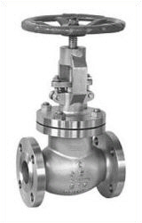
Image of a typical Gate Valve.

CONSTRUCTION OF A GATE VALVE

Gate Valves consists of three main parts: body, bonnet, and trim. The body is generally connected to other equipment by means of flanged, screwed or welded connections. The bonnet, which containing the moving parts, is attached to the body, usually with bolts, to permit maintenance. The valve trim consists of the stem, the gate, the disc or wedge and the seat rings.
DISKS OF A GATE VALVE

Gate Valves are available with different disks or wedges. Ranging of the gate valves is usually made by the type of wedge used.

The most common were:
Solid wedge is the most commonly used disk by its simplicity and strength.
A valve with this type of wedge can be installed in each position and it is suitable for almost all liquids. The solid wedge is a single-piece solid construction, and is practically for turbulent flow.
Flexible wedge is a one-piece disc with a cut around the perimeter to improve the ability to correct mistakes or changes in the angle between the seats.
The reduction will vary in size, shape and depth. A shallow, narrow cut gives little flexibility but retains strength.
A deeper and wider cut, or cast-in recess, leaves little material in the middle, which allows more flexibility, but compromises strength.
Split wedge is self-adjusting and selfaligning to both seats sides. This wedge type consists of two-piece construction which seats between the tapered seats in the valve body. This type of wedge is suitable for the treatment of non-condensing gases and liquids at normal temperatures, particularly corrosive liquids.

Image of the most common wedges.


STEM OF A GATE VALVE

The stem, which connects the handwheel and disk with each other, is responsible for the proper positioning of the disk. Stems are usually forged, and connected to the disk by threaded or other techniques. To prevent leakage, in the area of the seal, a fine surface finish of the stem is necessary.

Gate Valves are classified as either:
Rising stem
Non rising stem

For a valve of the rising stem type, the stem will rise above the handwheel if the valve is opened. This happens, because the stem is threaded and mated with the bushing threads of a yoke. A yoke is an integral part from a rising stem valve and is mounted to the bonnet.

For a valve of the non rising stem type, there is no upward stem movement if the valve is opened. The stem is threaded into the disk. As the handwheel on the stem is rotated, the disk travels up or down the stem on the threads while the stem remains vertically stationary.

The two links (on the right above) to detailed (large) drawings of both stem types, tell you more, as what I can tell you here.

SEATS OF A GATE VALVE

Seats for gate valves are either provided integral with the valve body or in a seat ring type of construction. Seat ring construction provides seats which are either threaded into position or are pressed into position and seal welded to the valve body. The latter form of construction is recommended for higher temperature service.

Integral seats provide a seat of the same material of construction as the valve body while the pressed-in or threaded-in seats permit variation. Rings with hard facings may be supplied for the application where they are required.

from www.wermag.org

THE MEANING OF VALVES - ONLY THE BASIC

Valves are mechanical devices that controls the flow and pressure within a system or process. They are essential components of a piping system that conveys liquids, gases, vapors, slurries et cetera.
Different types of valves are available: gate, globe, plug, ball, butterfly, check, diaphragm, pinch, pressure relief, and control valves. Each of these types has a number of models, each with different features and functional capabilities. Some valves are self-operated while others manually or with an actuator or pneumatic or hydraulic is operated.

Functions from valves are:
Stopping and starting flow
Reduce or increase a flow
Controlling the direction of flow
Regulating a flow or process pressure
Relieve a pipe system of a certain pressure

There are many valve designs, types and models, with a wide range of industrial applications. All satisfy one or more of the functions identified above.

Valves are expensive items, and it is important that a correct valve is specified for the function, and must be constructed of the correct material for the process liquid.

CLASSIFICATION OF VALVES
The following are some of the commonly used valve classifications, based on mechanical motion:
Linear Motion Valves. The valves in which the closure member, as in gate, globe, diaphragm, pinch, and lift check valves, moves in a straight line to allow, stop, or throttle the flow.
Rotary Motion Valves. When the valve-closure member travels along an angular or circular path, as in butterfly, ball, plug, eccentric- and swing check valves, the valves are called rotary motion valves.
Quarter Turn Valves. Some rotary motion valves require approximately a quarter turn, 0 through 90°, motion of the stem to go to fully open from a fully closed position or vice versa.

Classification of valves based on motionValve types    Linear motion   Rotary motion   Quarter turn
Gate Valv                                                                          x
Globe valve                                                                       x
Plug valve                                                                                                     x                   x
Ball valve                                                                                                      x                   x
Butterfly valve                                                                                               x                   x
Swing check valve                                                                                         x
Diaphragm valve                                                               x
Pinch valve                                                                       x
Safety valve                                                                      x
Relief valve                                                                       x

CLASS RATINGS
Pressure-temperature ratings of valves are designated by class numbers. ASME B16.34, Valves-Flanged, Threaded, and Welding End is one of the most widely used valve standards. It defines three types of classes: standard, special, and limited. ASME B16.34 covers Class 150, 300, 400, 600, 900, 1500, 2500, and 4500 valves.

VALVE BODY
The Valve body is the first boundary of a pressure valve. He serves as the main element of a valve assembly because it is the framework that holds all the parts together. The valve-body ends are designed to connect the valve to the piping or equipment nozzle by different types of end connections, such as butt or socket welded, threaded or flanged.

Valve bodies are cast or forged in a variety of forms and each component have a specific function and constructed in a material suitable for that function.
Image of a standard Gate Valve.
GATE VALVE BODY


VALVE BONNET

The cover for the opening in the body is the valve bonnet, and is the second most important boundary of a pressure valve. Like valve bodies, bonnets are in many designs and models available.

A bonnet acts as a cover on the valve body, is cast or forged of the same material as the body. It is commonly connected to the body by a threaded, bolted, or welded joint. During manufacture of the valve, the internal components, such as stem, disk and actuator, are put into the body and then the bonnet is attached to hold all parts together inside.

VALVE TRIM

Valve's trim is a collective name for the replaceable parts, in a valve. A typically valve design includes a disk, seat, stem, and sleeves needed to guide the stem.

VALVE DISK
The disc is the part which allows, throttles, or stops flow, depending on its position. In the case of a plug or a ball valve, the disc is called plug or a ball. The disk is the third most important primary pressure boundary. With the valve closed, full system pressure is applied across the disk, and for this reason, the disk is a pressure related component.
Disks are usually forged, and in some designs, hard surfaced to provide good wear properties. Most valves are named, according to the design of their disks.

VALVE SEAT(S)

A valve may have one or more seats. In the case of a globe or a swing-check valve, there is usually one seat, which forms a seal with the disc to stop the flow. In the case of a gate valve, there are two seats; one on the upstream side and the other on the downstream side. A gate valve disc has two seating surfaces that come in contact with the valve seats to form a seal for stopping the flow.

The seat ensure the seating surface for the disk. For a good sealing, a fine surface finish from the seating area is necessary.
In some designs, the body is machined to serve as the seating surface, in other designs, forged seal rings are threaded or welded to the body.
To improve the wear resistance of the seat or seal rings, the surface is often hard faced.

VALVE STEM

The valve stem provides the necessary movement to the disc, plug or the ball for opening or closing the valve, and is responsible for the proper positioning of the disk. It is connected to the valve handwheel, actuator, or the lever at one end and on the other side to the valve disc. In gate or globe valves, linear motion of the disc is needed to open or close the valve, while in plug, ball and butterfly valves, the disc is rotated to open or close the valve.
Stems are usually forged, and connected to the disk by threaded or other techniques. To prevent leakage, in the area of the seal, a fine surface finish of the stem is necessary.

There are five types of valve stems:
Rising Stem with Outside Screw and Yoke
The exterior of the stem is threaded, while the portion of the stem in the valve is smooth. The stem threads are isolated from the flow medium by the stem packing. Two different styles of these designs are available; one with the handwheel attached to the stem, so they can rise together, and the other with a threaded sleeve that causes the stem to rise through the handwheel. This type of valve is indicated by "O. S. & Y." is a common design for NPS 2 and larger valves.
Rising Stem with Inside Screw
The threaded part of the stem is inside the valve body, and the stem packing along the smooth section that is exposed to the atmosphere outside. In this case, the stem threads are in contact with the flow medium. When rotated, the stem and the handwheel to rise together to open the valve.
Nonrising Stem with Inside Screw
The threaded part of the stem is inside the valve and does not rise. The valve disc travels along the stem, like a nut if the stem is rotated. Stem threads are exposed to the flow medium, and as such, are subjected to the impact. That is why this model is used when space is limited to allow linear movement, and the flow medium does not cause erosion, corrosion or abrasion of the stem material.
Sliding Stem
This valve stem does not rotate or turn. It slides in and out the valve to open or close the valve. This design is used in hand-operated lever rapid opening valves. It is also used in control valves are operated by hydraulic or pneumatic cylinders.
Rotary Stem
This is a commonly used model in ball, plug, and butterfly valves. A quarter-turn motion of the stem open or close the valve.

on the right above of this page, you will find some links to detailed (large) images of rising and non rising stem valves.

VALVE STEM PACKING

For a reliable seal between the stem and the bonnet, a gasket is needed. This is called a Packing, and it is fitted with e.g. the following components:
Gland follower, a sleeve which compresses the packing, by a gland into the so called stuffing box.
Gland, a kind of bushing, which compressed de packing into the stuffing box.
Stuffing box, a chamber in which the packing is compressed.
Packing, available in several materials, like teflon, elastomeric material, fibrous material et cetera.
A backseat is a seating arrangement inside the bonnet. It provides a seal between the stem and bonnet and prevents system pressure from building against the valve pakking, when the valve is fully open. Back seats are often applied in globe valves.

Image of a typical sealing assembly.
TYPICAL SEALY ASSEMBLY


An important aspect of the life time of a valve is the sealing assembly. Almost all valves, like standard Ball, Globe, Gate, Plug and Butterfly valves have their sealing assembly based upon shear force, friction and tearing.
Therefore valve packaging must be properly happen, to prevent damage to the stem and fluid or gas loss. When a packing is too loose, the valve will leak. If the packing is too tight, it will affect the movement and possible damage to the stem.


VALVE YOKE

A Yoke connects the valve body or bonnet with the actuating mechanism. The top of the yoke holding a yoke nut, stem nut, or yoke bushing and the valve stem passes through it. A yoke usually has openings to allow access to the stuffing box, actuator links, et cetera Structurally, a yoke must be strong enough to withstand forces, moments, and torque developed by the actuator.

VALVE YOKE NUT

A yoke nut is an internally threaded nut and is placed in the top of a yoke by which the stem passes. In a gate valve e.g., the yoke nut is turned and the stem travels up or down. In the case of globe valves, the nut is fixed and the stem is rotated through it.

VALVE ACTUATOR

Hand-operated valves are usually equipped with a handwheel attached to the valve's stem or yoke nut which is rotated clockwise orcounter clockwise to close or open a valve. Globe and Gate Valves are opened and closed in this way.
Hand-operated, quarter turn valves, such as Ball, Plug or Butterfly, has a lever for actuate the valve.
There are applications where it is not possible or desirable, to actuate the valve manually by handwheel or lever. These applications include:
Large valves that must be operated against high hydrostatic pressure
Valves they must be operated from a remote location
When the time for opening, closing, throttle or manually controlling the valve is longer, than required by system-design criteria

These valves are usually equipped with an actuator.
An actuator in the broadest definition is a device that produces linear and rotary motion of a source of power under the action of a source of control.

Basic actuators are used to fully open or fully close a valve. Actuators for controlling or regulating valves are given a positioning signal to move to any intermediate position. There a many different types of actuators, but the following are some of the commonly used valve actuators:
Gear Actuators
Electric Motor Actuators
Pneumatic Actuators
Hydraulic Actuators
Solenoid Actuators

SUMMARY

On this page are defined a number of basic information from valves.
As you may have seen in the main menu "Valves", you can find also information about several and often applied valves in Petro and chemical industry.
It can give you an impression, and good understanding of the differences between the various types of valves, and how these differences affect the valve function. It will help to a proper application of each type of valve during the design and the proper use of each type of valve during operation.

So If you know much about valve, please answer the questions, what kind of the name of valve below ?


Monday, October 3, 2011

HARI INI AKU MAU BICARA MENGENAI MAKNA SEBUAH MIMPI

Kalau cerita mengenai mimpi sebuah sesuatu yang hil yang mustahal untuk di percayai karena mimpi itu ibarat sebuah cerita di alam bawah sadar kita kemungkinan adalah sesuatu keinginan, harapan dan khayalan yang selama ini diharapkan di alam sadar kita yang tak mungkin kita capai secara utuh.

Mimpi itu semacam suatu pengalaman pribadi dan merupakan suatu penomena yang universal dan dengan demikian memainkan peranan penting dalam pembentukan kebudayaan manusia. Dan hampir dapat dipastikan bahwa semua orang pernah bermimpi.

Namun tidak semua mimpi adalah benar dan otentik. Tapi mimpi para nabi dan kekasih Allah adalah Mimpi yang merupakan wahyu dari Allah yang benar dan sakral. Mimpi orang-orang saleh hampir selalu benar dan bermakna. Ada sebagian mimpi yang berasal dari setan dan dengan demiikian menyesatkan. Mimpi lain mungkin disebabkan oleh masalah-masalah fisik atau phisologis seperti gangguan perut atau gangguan emosi. Karenanya penting kiranya dapat membedakan mimpi yang benar dari khayalan kosong dan mimpi ilhami dari godaan setan.

Dan agar kita memahami Makna Arti sebuah Mimpi lebih baik , ada sebuah buku telah diterbitkan yang berjudul "ENSIKLOPEDIA TAKWIL MIMPI ISLAM - IBNU SIRIN. " Editor Muhammad M. Al Akili.
Diedit dari judul aslinya "MUNTAKBAB AL KALAM FI TAFSIR AL ABLAM" .
Meskipun buku tesebut memandang mimpi dari pengertian dari sudut pandang Islam. Tapi disini di kebenaran yang menjadi landasannya dan yang disingkapkannya bersifat universal dan diakui sejak dulu. Karena buku tersebut ditujukan kepada orang yang dengan serius memandang mimpi sebagai aspek penting dari kehidupan, keimanan dan keadaan psikologis mereka.

Buku tersebut pun merupakan buku pedoman Islami yang pertama tentang takwil mimpi yang otentik. Diharapkan kamus mimpi ini akan bermanfaat bagi bidang budaya dan spiritual , lebih-lebih lagi bagi para pencari kebeneran.

Bila anda ingin menafsiran mimpi anda melalui Buku ini, anda bisa mengisi cerita mimpi di dalam kolom komentar dan saya akan coba untuk menjawab pertanyaan anda berdasarkan buku tersebut.


Kuala Lumpur, 3 Oktober 2011 jam 11.00 pm

HARI INI AKU MAU BICARA TENTANG CINTA...

Hari ini aku akan bicara mengenai cinta dan makna dari sebuah cinta..
Banyak orang yang terlena karena cinta dan banyak orang yang terlupa karena cinta
Cinta itu khan selama nya kekal bilamana ada saling percaya antara dua insan yang bercinta
Cinta itu tak kan selamanya murni bila tak ada syair lagu kehidupan yang menyertai di dalamnya.

Saya mencoba mengkutip dari sebuah buku catatan "Pertemanan Remaja yang ditulis di bulan Juni tahun 1971, mengenai pandangan tiap-tiap profesi mengenai Cinta,

Kalau cinta menurut seorang Insinyur Civil  bahwa cinta itu ibarat tiang baja yang kokoh tapi bisa roboh ditiup angin sepoi-sepoi..
Kalau Cinta menurut seorang Pelaut : Cinta itu adalah sebuah daratan yang menenggelamkan
Kalau Cinta menurut seorang Tentara ; Cinta itu adalah lebih tajam dari ujung bayonet
Kalau Cinta menurut seorang Wartawan : Cinta itu seperti koran delapan halaman yang sukar di baca
Kalau Cinta menurut seorang Polantas : Cinta itu ibarat jalan yang berkelok-kelok yang harus dilalui dengan hati-hati karena banyak rambu-rambu yang mengiasinya.

Dan pandangan lain mengenai cinta adalah :

Cinta itu mengakibatkan Cemburu..
     Cemburu mengakibatkan Dendam
          Dendam itu mengakibatkan Sakit Hati
               Sakit Hati Kadang Bikin Putus Asa
                  Dan putus asa mengakibatkan Patah Hati....

Makanya dari pada sakit hati lebih baik sakit gigi ini.....
Janganlah bermain cinta bilamana tak sanggup menghadapi cobaan cinta.

Itulah sebaik pembuka mengenai penomena sebuah cinta dimana kadang bikin orang sakit hati, kadang bikin orang cemburu dan kadang bisa bikin orang bahagia. Dan bahagia karena cinta itulah yang diharapkan bagi setiap insan yang mengalami cinta.

Kenalilah dan Cintailah Agamamu sebelum kamu mengenai Cinta Manusia.
Kenalilah dan Hayatilah Agamamu sebelum kamu menghayati sebuah cinta manusia.
Jagalah Perasaan Tuhanmu, yang menjadikanmu hidup sebelum kamu memahami perasaan cinta manusia.
Pahamilah Ayat demi Ayat di dalam Kitab Sucimu sebelum kamu menghayati cinta manusia.

Hidup ini indah bilamana kita memahami makna sebuah cinta yang sesungguhnya..

 
Kuala Lumpur, 3 Oktober 2011 . pukul 10.24 PM.